Section 6 The Enigma Machine
Subsection 6.1 Cipher Machines
Several inventions in the 1800's dramatically changed the nature of communication techniques and increased the need for encrypting information. The invention of the telegraph in the mid-1800s vastly increased the speed of communication. Once telegraph lines were laid between locations, messages were transmitted very quickly. However lines could be tapped, so communicating by telegraph increased the need for greater security. Since telegraph companies charged by the “word” in transmissions, communication techniques favored efficient ways to exchange information. Thus, the use of code books, both public and secret, increased dramatically.


The second invention in the late 1800's/early 1900's was the development of communication by radio. This made long distance communication much faster and easier (no telegraph wires needed), but anyone could intercept and overhear the messages communicated by radio. So the need for secure methods of communicating became even more important. As communication technology progresses in these important directions, we also see a corresponding increase in the complexity of code and cipher techniques. In particular, we see the development of mechanical and electrical machines for encrypting information. These cipher machines were often dominated by combinations of rotors and were prevalent from the 1920s to the 1970s.


Subsection 6.2 Enigma Mechanics
The Enigma machine is one of the most famous cipher machines. It was invented in 1918 by German inventor and electrical engineer, Arthur Scherbius. The original invention was adapted by the German military and used extensively during World War II. The German navy began using the Enigma machine in 1926 and the German army began using the Enigma machine in 1928.


An Enigma machine consists of a keyboard, a plugboard, a scambling unit consisting of 3-4 rotors and a reflector, and a display board. The plaintext is entered on the keyboard. When the keyboard letter is pressed, it creates an electrical circuit which travels through the plugboard, the scrambling unit, and then back through the plugboard to light a lamp on the display board giving the ciphertext letter. We will examine each of these parts of the machine in detail, but first the brief video below shows an Enigma machine in action.
The keyboard is where the plaintext letter is entered and operates similarly to a typewriter. It contains only the 26 letters of the alphabet and has no options for numbers or spaces. Pressing the keyboard moves as least one of the rotors and initiates an electric current.

The plugboard or steckerboard was located in the front of the machine and had switches for each of the 26 letters of the alphabet. This was similar to a telephone switchboard at the time. Cables (or steckers) were used to connect switches that produced a corresponding swap of two letters. The number of cables that were used varied at different times during the war. The plugboard was not present in the commerical version of Enigma designed by Scherbius but was added for the military version.

The scrambling unit consisted of 3-4 rotors depending on the type of Enigma machine and a reflector. Army and air force Enigma machines used three rotors, and eventually naval Enigma machines used four rotors. We will primarily discuss how the three rotor machines worked.

For the scrambling unit portion of the Enigma machine, if viewed from the front of the machine, the current passes through
the rightmost rotor
the middle rotor
the leftmost rotor
the reflector
back through the leftmost rotor
back through the middle rotor
back through the rightmost rotor
Each rotor consisted of 26 nodes on each side (one side has pin contacts and the other side has flat contacts). These two sets of nodes have wires connecting one to the other. This wiring created a one-to-one switching of letters in the alphabet (that is, a permutation of the alphabet). For detailed images of how to wire a rotor, see http://enigmamuseum.com/replica/#rotorwiring.
On the right hand side of each rotor was a cogwheel with 26 teeth. On the left hand side of each rotor there is a metal ring with either the numbers (1-26) or the letters (A-Z). This metal ring could be shifted relative to the wiring by means of a clip. This clip specifies the ring setting of each rotor. Each rotor would be placed into the machine with one of these numbers of letters showing in a display board. The letters for all of the rotors in the machine is often called the indicator setting. This doesn't create additional initial settings, but rather disguises the displayed rotor setting.


The rotors were connected together and placed into the machine as a unit of three or four rotors. Each rotor was then rotated to a given starting letter. For three rotor machines, the rotors could be arranged in any order. For four rotor machines, three of the rotors could be placed in any order, but the fourth rotor was limited. (Special fourth rotors and thinner reflectors were designed to take the place of the entire reflector.)
The reflector consisted of 26 nodes with wires that swapped thirteen pairs of letters and sent them back through the rotors in reverse. For the three rotor machines, the reflector was a fixed part of the machine and could not be changed. More details on the scrambling unit is below.
The last part of the enigma machine was the display board or lampboard. Pressing the letter on the keyboard initiated a current which traveled through the keyboard, plugboard, and scrambling unit to light up a letter in the lampboard. Enigma operators would record this letter as the ciphertext for the plaintext letter they entered on the keyboard.


The important part of the scrambling unit is that every time a letter is pressed on the keyboard a stepping action changes the location of at least one rotor, so that the next letter is encrypted in a very different way. Note this stepping action occurs when the key is pressed and before the current is sent through the circuit. The mechanics of the stepping action are very interesting and sometimes produced an unexpected stepping of the middle rotor. Pressing a letter on the keyboard moves three levers connected to each rotor.
The first lever is on the outside of the rotor 1 (to the right of rotor 1 if viewed from the front of the machine). It is connected to a gear on the rotor with 26 teeth. Thus, this lever moves the rotor to the next node every time a letter is pressed on the keyboard.
The second lever is located between the first and second rotors. It is wider than lever 1, and is connected to both a gear with 26 teeth and the edge of rotor 1 which has a notch in only one position. This lever becomes active only when it engages the single notch on rotor 1. When engaged it moves rotor 1 (via the notch) and rotor 2 (via the gear). Rotor 1 is moved by lever 1 at every step, so this additional effect of movement by lever 2 is not noticable.
Lever 3 is similar to lever 2 but located between rotor 2 and rotor 3. When lever 3 hits the notch on rotor 2, it moves rotor 2 and rotor 3. Since rotor 2 is not moving at every step this produces an additional stepping of rotor 2.
This is easier to see in action in the video below. Note, the levers are at the back of the rotors so this shows the action from the rear of the machine. Thus, the levers are to the left of a rotor rather than the to the right of a rotor.
In order to use the Enigma to exchange messages, two machines had to be set up in exactly the same way. This required choosing
- three (or four) rotors from the set of rotors
- the ring setting for each rotor
- the order the rotors went into the machine
- the indicator setting for all three (or four) rotors
The total number of rotors that could be chosen from varied throughout the war and by type of traffic. Air force and army machines initially had a set of three rotors but it was expanded to a set of five rotors by the end of the war. Naval Enigma machines had as many as eight different rotors to choose from (not including the special fourth rotor). To communicate these settings code books with the settings for an entire month were used as in Figure 6.14.

The combined action of the keyboard, plugboard, rotors and reflector is illustrated in a simpler form in the sage code below. It illustrates a mini-enigma with 6 letters per rotor and a plugboard with 2 cables to swap letters is illustrated in the sage code below. The red dot indicates the position of the notch which moves the next rotor. The notch would be present on the third rotor, but it wouldn't have an effect when the rotor was in that position so it is not shown.
Computation 6.15. Mini Enigma Simulator.
Note that the reflector serves two very important roles. First, it creates a reciprocal cipher. That is, if A is encrypted as B, then B is encrypted as A. This always happens because the reflector swaps letters. This is very important in terms of ease of use because it means the setup for encryption and decryption are the same. The second important feature is that a letter can never be encrypted as itself. This information was very helpful to cryptanalysts.
The Enigma machine is quite complicated. To get a feel for how this works we will start with two simpler models. The first has only one rotor which steps. The second is a paper model and has three rotors and a reflector, but does not have a plugboard.
Subsection 6.3 A One Rotor Version
In the interactive one rotor machine below, to encrypt the letter A, we find A on the outside wheel, then we see what number it matches with on the inside wheel. In this case, it matches with 1. Now we find the other 1 on the inside wheel and see what letter it matches with. In this case, it matches with W so that A encrypts as W. In this case we are imagining that a wire connects the two numbers which are the same. To encrypt the next letter, say an A again, we move the rotor one step and repeat the process. For Step 1, A now encrypts as K, and we look for the two 10s on the inner wheel.
Computation 6.16. A One Rotor Enigma.
Activity 6.1.
Encrypt the message SECRET by encrypting the letter S, with Step 0, E, with Step 1, and C with Step 2, etc. That is, after encrypting each letter rotate the rotor by one step.
Encrypt the message SECRET by encrypting the letter S, with Step 10, E, with Step 11, and C with Step 12, etc. That is, after encrypting each letter rotate the rotor by one step. But start with Step 10 instead of Step 0.
Decrypt the message FDBYYW in the same manner. Start at step 0 for the first letter and then rotate the rotor by one step for each of the next letters.
-
We want to explore how many ways there are to create the wiring for this type of rotor.
Suppose a rotor only had 4 letters, ABCD. How many ways can the rotor be wired so that the letters are swapped? That is, if A is wired to C, then C is wired to A. Also, B and D must be wired in this case, since that is the only option left. List all ways to wire the 4 letters with two wires. (Each wire swaps a pair of letters.)
Suppose a rotor has 6 letters, ABCDEF. How many ways can the rotor be wired so that the letters are swapped? List all ways to wire the 6 letters with three wires. (Each wire swaps a pair of letters.)
Suppose a rotor has 8 letters, ABCDEFGH. How many ways can the rotor be wired so that the letters are swapped? There should be four wires here and each wire swaps a pair of letters. Don't try to write them all down try to understand the pattern from the first two examples.
How many ways to wire the rotor with all 26 letters using 13 wires where each wire swaps two letters?
-
A group of Polish mathematicians at the Polish Cipher Bureau were able to crack the Enigma machine without ever seeing one! The first thing they had to figure out is how the rotors were wired. To see the idea of how this works encrypt each of the following pairs of repeated letters. For each pair, encrypt the first letter with Step 0 and the second letter with Step 1. The first few are filled in for you, encrypt the rest in table below.
AA BB CC DD EE FF GG HH II JJ KK LL MM WK LQ RW NN OO PP QQ RR SS TT UU VV WW XX YY ZZ \(\;\)
Subsection 6.4 The Paper Enigma
Make your own paper enigma with images/paper_enigma.pdf.
How to use the paper enigma.
- Cut out the rotors following the dotted lines. Do not cut off the arrows. Those are the notches to indicate when to move the next rotor.
- You can cut little slits in the paper to insert the rotors. Cut three little slits along the top and bottom line, just long enough for the rotor to fit. (Cut the top line of each of the three gray boxes at the top of the paper enigma. Cut three similar slits along the bottom.)
- For the initial message, place rotor I in the leftmost spot with M along the top row. Rotor II should be the middle rotor with C along the top row. Rotor III should be in the rightmost spot with K along the top row. See Figure 6.17.

Figure 6.17. Setting up the Paper Enigma - The rightmost rotor moves up one space as you enter the letter on the keyboard. That is, always move the rightmost rotor up one space before encrypting a letter, even the very first time. So that your starting position should be Figure 6.18.

Figure 6.18. Move rightmost rotor one position - To simulate the wiring of a rotor, match up letters between the right and left side of each rotor. For example, the ciphertext letter Q enters straight across into the right side of the rightmost rotor, as a letter D, then you find the D on the left hand side of that rotor, then go straight across from the left hand D to the center rotor. Repeat similarly for each rotor and the reflector. A diagram of this for the first letter is given in Figure 6.19. This shows that the ciphertext letter Q corresponds to the plaintext letter E at the first step.

Figure 6.19. Move rightmost rotor one position - Using the notch/arrow. If the \(\uparrow\) appears in the top row of a rotor, at the next step move that rotor and the rotor to the left of the arrow up one space.
Activity 6.2.
With your paper enigma machine, place the rotors in the machine in order III,II,I (III is left most, II is middle, I is right most) and use initial key to FYS and decrypt the ciphertext CMQZX GNL. Remember to move the right most rotor once BEFORE decrypting each letter, even the first letter. Try at least a few of these by hand to understand the machine, but you can check your work with the Paper Enigma simulator below.
With your paper enigma machine, place the rotors in the machine in order II,I,III (II is left most, I is middle, III is right most) and use initial key to YES and decrypt the ciphertext LDNCA. Remember to move the right most rotor once BEFORE decrypting each letter, even the first letter.
How many ways are there to arrange the rotors in the paper enigma?
How many choices of keys for the paper enigma once the rotors are in place?
How many total initial settings for the paper enigma? (Arrange rotors AND pick key.)
By the end of the war, the Enigma machine was set up so that there were 5 rotors and they chose 3 of them to put in the machine. How many ways are there to do this?
Computation 6.20. Paper Enigma Simulator.
Subsection 6.5 Permutations and Letter Chains
With the development of the Enigma machine and other cryptographic machines, we begin to see more mathematicians being recruited into cryptology. Some of the earliest work on attacking the Enigma machine occurred at the Polish Cipher Bureau (Biuro Szyfrów, pronunciation from Wikipedia). They recruited mathematicians to work on cryptology and attack the Enigma machine. The three most famous ones are Marian Rejewski (pronunciation from Wikipedia), Jerzy Różycki (pronunciation from Wikipedia), and Henryk Zygalski (pronunciation from Wikipedia).

The Polish mathematicians were initially aided in their work by materials that French officers received from a German defector who provided documents that described how the Enigma machine worked (minus the actual wiring of the rotors) and a code book of settings for the Enigma machine for a certain period of time.
Recall that the Germans used extensive code books which specified the initial settings of the machine. At this time, these included which rotors were used and in which order they were placed into the machine, the ring setting for each rotor and the indicator setting for each rotor, and the plugboard settings. (Later the indicator setting would be transmitted differently.)
It is not cryptographically secure to send many messages using the exact same key. To avoid sending all the messages for a single day using the same key, each Enigma operator would additionally select a three-letter message key. Initially, this three-letter key would be repeated to form a six-letter message (e.g. CKWCKW) which would be encrypted with the day settings and transmitted. Then the initial settings of the rotors would be changed to the message settings (e.g., CKW) and the message would be transmitted. The message key was repeated to allow the receiver of the message to check for garbles that may have occurred in transmission. However, this “repeated encryption” of the message key allowed Rejewski to use theorems about permutations to solve for the wiring of the rotors and find the daily settings.
Worksheet Investigation: Letter Chains
1.
Use the mini enigma in Computation 6.15 to encrypt ABCABC. That is, encrypt A with step 0, B with step 1, C with step 3, etc. Similarly encrypt each group of six letters below, starting back at step 0 for each group.
| ABCABC | \(\qquad \qquad\) |
| BEDBED | |
| CFACFA | |
| DABDAB | |
| EDEEDE | |
| FCFFCF |
2.
Find the permutation for the letters A,B,C,D,E,F given by step 0 of the mini enigma. For example, A goes to B and B goes to A.
\(P_0=\)
| A | B | C | D | E | F |
| B | A |
3.
Find the permutation for the letters A,B,C,D,E,F given by step 3 of the mini enigma.
\(P_3=\)
| A | B | C | D | E | F |
| C |
4.
Find \(P_3(P_0)\text{.}\) That is, find the permutation given by applying \(P_0\) first and then \(P_3\text{.}\)
| A | B | C | D | E | F |
| D |
5.
If you look carefully at Exercise 1, you should be able to see the permutation \(P_3(P_0)\) in your table. Where is it and why?
We will construct a set of double encrypted message keys and show how the ciphertext from these encrypted message keys could be used to recover information about the Enigma machine. We select twenty six sets of three letters, repeat them, and then encrypt them with the paper enigma or paper enigma simulator with the settings of rotor I, II, III (in that order from left to right) and the initial rotor positions of MCK. The sets are selected so that every letter in the alphabet occurs once in each spot.
| PT | CT | PT | CT | PT | CT |
| ANTANT | TMLHSM | BOXBOX | VVSLBS | CAPCAP | WRFDIL |
| DRYDRY | HAQCFE | ELKELK | QEBPZV | FIGFIG | KFDWAH |
| GTIGTI | NXJIUC | HBOHBO | DSAAOA | IJNIJN | OUCGGZ |
| JKLJKL | MGTKCP | KGBKGB | FKKJJF | LMHLMH | ZNMBDG |
| MSUMSU | JBVQNR | NEWNEW | GLRUHQ | ODDODD | IQGSMJ |
| PFFPFF | UIPERB | QQQQQQ | EDYMWW | RCARCA | YZOTKO |
| SUMSUM | XJHOTT | THETHE | APZREY | UPSUPS | PHXNVX |
| VVVVVV | BOUYPK | WWJWWJ | CYIFQD | XYZXYZ | SWEZXN |
| YZRYZR | RCWVLU | ZXCZXC | LTNXYI |
We now construct letters chains between the first and the fourth letter of the ciphertext. We use the first and the fourth letters because they were encrypted with the same letter in the underlying plaintext. We'll see why that's important later. The first ciphertext is TMLHSM. The first letter is T and the fourth letter is H, so we start our letter chain with (TH). Then we find a ciphertext that starts with H. The ciphertext corresponding to DRYDRY is HAQCFE. We now extend our letter chain with the first and fourth letters here. That is, the letter chain is now (THC). We next use ciphertext CYIFQD to continue the letter chain to (THCF). Repeating this process we obtain (THCFJQPNISZBY). Note that cipher text YZOTKO links back to the starting letter of our chain so we close the chain. We haven't used the entire alphabet yet, so we start with a letter of the alphabet not in the first letter chain, such as A. We use the ciphertext APZREY to start our new letter chain (AR). Continuing through the same process we obtain (ARVLXOGUEMKWD). Thus, from the first and fourth letter chains for this setting we get two chains of length 13, namely
(ARVLXOGUEMKWD)(BYTHCFJQPNISZ).
Similarly, we can find the letter chains for second and fifth letters to get
(MSOPEZKJTYQ) (AF) (BNDWXUGCLHV) (IR).
The letter chains for third and sixth letters are
(A) (BVRQENIDHTP) (CZYWUKFLMGJ) (O) (S) (X).
We can use Table 6.22 to construct permutations given by this initial setting I:M,II:C,III:K. We will call \(P_1:PT \to CT\) the permutation that describes how each of the first letters in the plaintext messages are enciphered. For example, the plaintext letter A is enciphered as T, so \(P_1(A)=T\text{.}\) It is helpful to remember that the Enigma machine is constructed so that encrypting and decrypting is the same. Thus, if \(P_1(A)=T\) then we also know \(P_1(T)=A\text{.}\)
A
B
C
D
E
F
G
H
I
J
K
L
M
N
O
P
Q
R
S
T
U
V
W
X
Y
Z
T
V
W
H
Q
K
N
D
O
M
F
Z
J
G
I
U
E
Y
X
A
P
B
C
S
R
L
We will also construct the permutation \(P_4\) which describes how each of the fourth letters in the plaintext are enciphered.
A
B
C
D
E
F
G
H
I
J
K
L
M
N
O
P
Q
R
S
T
U
V
W
X
Y
Z
H
L
D
C
P
W
I
A
G
K
J
B
Q
U
S
E
M
T
O
R
N
Y
F
Z
V
X
The Polish mathematicians did not have this information, but we will see how they were able to discover information about these permutations based solely on the encrypted message keys and corresponding letter chains. To do this we next create the composition of permutations \(P_4\) and \(P_1\text{.}\) We first apply the permutation \(P_1\) to each letter and then apply the permutation \(P_4\) to the output letter from \(P_1\text{.}\) For example,
Note that
so that the reciprocal property no longer holds. This gives
| A | B | C | D | E | F | G | H | I | J | K | L | M | N | O | P | Q | R | S | T | U | V | W | X | Y | Z |
| R | Y | F | A | M | J | U | C | S | Q | W | X | K | I | G | N | P | V | Z | H | E | L | D | O | T | B |
Note that typically we write composition of functions right to left \(P_{4}(P_1)=P_4\circ P_1=P_4 P_1\text{.}\) But this is a notational choice and Rejewski wrote his composition of functions in the opposite order, from left to right. So if you are interested in reading any of Rejewski's historical documents you'll note that all his permutations are written in a different order.
We next write the composition permutation \(P_{4}(P_1)\) in cycle notation. \(P_{4}(P_1)=\)(ARVLXOGUEMKWD)(BYTHCFJQPNISZ) and we should notice one of the important results that Rejewski used to crack the Enigma machine. We see that \(P_{4}(P_1)\) is given by the letter chains from the ciphertext messages!
Why is this true? It has to do with the \(P_1\) and \(P_4\) acting on the same plaintext letter and the fact that the encryption and decryption process are the same. Let \(PT_1=PT_4\) be the first letter of the plaintext which is the same as the fourth letter of the plaintext, \(CT_1\) be the first letter of the ciphertext, and \(CT_4\) be the fourth letter of the ciphertext. Then
Thus,
Thus we see that the composition permutation \(P_{4}(P_1)\) gives the letter chain where \(CT_1\) goes to \(CT_4\text{.}\)
The more impressive thing is that Rejewski discovered he could work backwards. That is, he could use the letter chains to find the permutations \(P_1\) and \(P_4\text{.}\) (Almost -- there's still some guess and check work left to do.)
| \(P_1= \qquad\) | A | R | V | L | X | O | G | U | E | M | K | W | D | \(\qquad\) | (=first letter chain) |
| T | Y | B | Z | S | I | N | P | Q | J | F | C | H | \(\qquad\) | (=second letter chain in reverse order) |
The magical thing is that this will always work except for finding where to start writing the cycle on the bottom. There are only 13 possibilities to check though and evidently Rejewski was aided by Enigma operators not making entirely random choices for the three letters message keys. Often they would just use the same letter and pick JJJ for their three letter message key.
Rejewski's theorems on permutations are summarized in the theorem below.
Theorem 6.26.
Rejewski's Idea: The cycle structure of the composition \(P_{4}(P_1)\) will always be pairs of cycles that can be matched up as above to produce \(P_4\) and \(P_1\text{.}\)
This theorem is actually true for any composition of permutations where each permutation is a product of transpositions (swaps of two letters).
Rejewski repeated the same process for 2nd and 5th ciphertext letter chains and 3rd and 6th ciphertext letter chains. He used the information for \(P_1, P_2, P_3, P_4, P_5, P_6\) together with the fact that \(P_{i+1}\) should be related to \(P_i\) by a rotation of the right rotor only. This process is based on the likelihood that the middle and left rotor will not move in the encryption of just six letters for most setting. (This process fails if the middle or left rotor moves during these first six letters.) This allowed him to cancel out the action of the left and middle rotor and focus on just the right rotor. The information from the German spy gave him the settings for machine; in particular the settings for the plugboards were known so he could also cancel those out. All of that information was combined to deduce the wirings for the rightmost rotor. He then had to wait for another day when a different rotor was in the rightmost spot to solve for the wirings of that rotor.
Once the wirings were known, the Polish Cipher Bureau could read German Enigma messages since they had the captured information about daily settings. However, once the daily setting information from the German spy ran out, they could also use the letter chains from the ciphertext of the repeated message keys to determine the initial settings. They built a machine, called a cyclometer, to construct the letter chains for all \(105,456=6 \times 26^3\) initial settings of the machine. (At that time, there were only three rotors to choose from, each with 26 possible starting positions.) Essentially the cyclometer connected simulations of two Enigma machines scrambling units, where the second one is stepped forward three positions from the first one to recreate the first to fourth letter chain in the ciphertext. When the current was active, it would light up all of the letters in a cycle or complimentary cycle for a letter chain at a given setting. The important point is that although the plugboards will change the specific letters in the letter chain cycles, they don't change the lengths of cycles. Thus, the Polish mathematics created a catalog of the lengths of all the cycles for each setting. Creating the catalog took a long time, but once it was ready daily keys could be obtained within 10-20 minutes.
While these letter chains and associated permutation theory were put to good use by Rejewski, Różycki, and Zygalski for breaking Enigma messages, as German protocol for encryption techniques changed, they developed many other techniques as well. A grill and clock method were useful early on for determining wheel settings and orders. When the protocol changed and repeated encryptions were no longer sent on daily indicator settings but on individually chosen operator settings, the catalog method no longer worked. An adaption of the catalog method which focused on which settings would allow letter chains of just a single letter was developed. Two different techniques were developed to do this. Rejewski built an electro-mechanical machine called the “bomba kryptologiczna” (cryptologic bomb) which simulated six Enigma machines (essentially three cyclometers). The bomba depended on relatively few letters being steckered to function. Zygalski created a method of perforated sheets to search for these settings. This technique was not dependent on the plugboard settings and was eventually used quite effectively. Construction of appropriate sets of perforated sheets took a long time. As the political situation became more dire, this important work of the Polish cryptographers was shared with the British and French and was very important to the work of the Bletchley Park codebreakers which we will discuss in the next section.
We conclude this section with a brief historical timeline about the Polish work.
1929. Twenty students including Rejewski, Różycki, Zygalski recruited for a cryptography class at the University of Poznan.
1929-1930. Rejewski, Różycki, Zygalski start working at the Polish Cipher Bureau.
1932. Hans-Thilo Schmidt (code name Asche) sells instructions for the German army Enigma machine to the French who share the information with the Polish. These materials include daily settings for September 1932 and October 1932.
1932. Rejewski used the repeated encryption of message keys and the information from the German defector to find the wirings of two rotors. The wheel orderings were constant for September and constant (but different) for October. He then used other methods to deduce the wiring of the last rotor and the reflector.
1933. Różycki and Zygalski joined Rejewski to work on breaking Enigma messages.
1933-35. Used grill method and clock method to determine orders and settings of wheels.
1936. The number of cables used in the plugboard changed from 6 to vary anywhere from 5-8. Cyclometer built to construct catalog of cycle lengths of letter chains.
November 1937. The reflector was changed in the Enigma machine from Reflector A to Reflector B and the catalog had to be reconstructed.
September 1938. Changed the indicator protocol. No longer sent the repeated encryptions of message keys using the daily setting. Each operator chose an indicator setting which was sent in the clear as part of the message preamble. The Enigma machines were reset to this indicator setting on the rotors and then the message setting was encrypted with the repeated encryption. Catalogs no longer worked.
December 1938. Two more rotors were added to the set of rotors. Previous methods were used to determine the wiring (on a channel that was still using the old indicator system.) Zygalski sheets and Rejewski's “bomba kryptologiczna” (cryptologic bomb) were developed. Political situation was deteriorating and invasion seemed imminent.
July 1939: The Polish work is shared with the British and French at a meeting near Warsaw. (Pyry)
September 1939. Germany invades Poland. Britain and France declare war on Germany.
October 1939. Polish mathematicians escape to France. They continue work on Enigma from Vichy France and North Africa.
1940. Complete sets of perforated sheets are constructed at Bletchley Park and a set is given to Rejewski, Różycki, Zygalski in France. These are used to break many Enigma messages (both in France and at Bletchley Park.)
January 1942. Rozycki dies traveling between North Africa and France. (The Lamoriciere is sunk.)
July 1943. Rejewski and Zygalski escape to Britain and work at a Polish Signals Battalion in Boxmoor near London.
Subsection 6.6 Cribs and Bombes
Our next section about cryptanalysis related to the Enigma machine moves to Bletchley Park in England. Bletchley Park was the World War II home for the Government Code and Cypher School (GC&CS). Its codebreakers included Alan Turing, Gordon Welchman, Hugh Alexander, Stuart Milner-Barry and many, many others. Mathematicians were also heavily recruited at Bletchley Park. The codebreaking work at Bletchley Park had many fascinating success stories, but in this section we will focus on the cryptanalysis of the Enigma machine and the work of Alan Turing.
The Polish work to break Enigma messages relied heavily on the repeated encryption of the message key and developing some electro-mechanical devices to help check the many potential initial settings. The codebreakers at Bletchley Park relied heavily on the Polish work, especially the deduction of the wirings of the rotors and the Zygalski sheets. The Zygalski sheets became ineffective in May of 1940 when the repeated encryption of the message key was discontinued. Fortunately, Alan Turing, Gordon Welchman and others were working on a new idea to use cribs to make deductions about inital settings. This required designing more elaborate machines, called bombes after the Polish bomba, to check all the possible initial settings very quickly.
In order to use a crib for decrypting ciphertext, it is necessary to know an exact word or phrase that will occur in the plaintext. Early decryption work allowed cryptanalysts to learn patterns in German messages that allowed them to discover many useful cribs. One main type of message that helped for cribs was weather reports that were sent at the same time everyday. According to Copelands's “The Essential Turing” other routine phrases that occurred often and became cribs include:
Wetter fuer die nacht (weather for the night)
Zusand ost waertiger kanal (situation eastern channel)
Feuere brannten wie befohlen (beacons lit as ordered)
Finding the location of cribs in the ciphertext was made easier by the property that the Enigma machine will never encrypt a letter as itself.
For an example, we will turn to a training manual for the Enigma machine that Turing wrote for use at Bletchley Park. This was known affectionately at Bletchley Park as the “Prof's Book”, but if more officially known as Turing's “Treatise on the Enigma”. In it, he describes how to use a matched matched plaintext/ciphertext pairing from a crib to find cycles of letters. We will refer to these at Turing loops. The ciphertext in the top row is paired with the plaintext in the bottom row. The full plaintext is “Keine Zusaetze Zumvorberiqt” which is German for “No additions to Preliminary Report.”
Example 6.28.

In this example, two main loops are shown, one in green and one in orange. These are the shortest possible loops since they involve only two letters at two different positions. There is a loop connecting A and E at positions 2 and 5. There is also a loop connecting E and I at positions 3 and 10. Remember that encryption and decryption is the same for Enigma so it doesn't matter if the letters are in the plaintext or the ciphertext to create a loops.

A plaintext/ciphertext pairing would produce a longer loop if it takes more steps to connect back to the starting letter. For example, if a crib produced the following ciphertext/plaintext pairing
| position | 1 | 4 | 6 | 9 |
| CT | D | N | N | Z |
| PT | K | K | Z | D |

Turing's solution is given Figure 6.31. A diagram showing all of these connections was known as a menu. Can you spot the mistake in Turing's menu?

The importance of the loops stems from Turing's idea for how to use them to design electrical circuits in the bombe machines. The bombe machines essentially consisted of multiple scrambling units of Enigma machines (no plugboards) connected together and could reject possible settings very quickly if they did not contain an appropriate electrical circuit corresponding to a loop. To illustrate how this works, we first consider how a loop would work if there were no cables connecting letters in the plugboard. Suppose we have the A-E loop at positions 2 and 5 as in Example 6.28. Then we must have an initial setting where A is encrypted as E and then three steps later in Enigma machine, A must also be encrypted as E. To test if this works for rotor setting AAA and wheels I,II,III we need to connect two Enigma machines in the following way.
Set machine 1 to setting AAA and wheels I,II,III. [Corresponding to position 2 in loop]
Set machine 2 to setting AAD and wheels I,II,III [Corresponding to position 5 in the loop which is 3 positions after position 2.]
Connect machine 1 to machine 2 so that the output of machine 1 becomes the input of machine 2. Type A on first machine. It should output E which becomes the input to the second machine. Then the second machine should output A. So with the machines wired together, we want to input A and see if the connected machines output A.
If not, change the wheel settings to AAB and AAE and try again. Then we would also need to try all possible arrangements of the rotors.
There is also some chance the middle wheel might turn in the process if the notch on that rotor is activated, so that must also be considered. This is already a lot of things to check and we have been ignoring the plugboard. However, Turing importantly realizes that loops are “characteristics of the crib which are independent of the Stecker.” [“Treatise on the Enigma”, p98] The loops will still happen even if the plugboard component is not present. They will just happen with different letters. For example, if the plugboard swaps A and K, and we remove the plugboard cables, now K will be the letter that goes to itself instead of A. We illustrate this idea with the mini enigma simulator. In the mini enigma simulator there is a C-F loop at positions 0 and 2.


The mini enigma has cables that swap A&C and E&F. If we remove all swaps in the plugboard, then there is still a two letter loop at positions 0,2. However, it is now an A-E loop instead of a C-F loop as in Figure 6.33. The C changed to A because of the AC swap in the plugboard, and the F changed to E because of the EF swap in the plugboard. (If you want to try this yourself in the code, change the second line of code from plug=[["A","C"],["E","F"]] to plug=[["A","A"],["E","E"]]. )


Turing's brilliant idea for designing the bombe was to work backwards. Find loops from ciphertext/plaintext pairings and use them to find rotor settings that would satisfy the loops. More precisely the goal was to use these loops to find stecker values for the letters in the loops or to determine that there is no possible set of stecker values and thus rule out the given setting. Multiple loops were necessary to narrow down the possibilities successfully. However, Gordan Welchman's important contribution for the addition of a diagonal board eventually allowed this technique to work with smaller cribs and no loops. Gordan Welchman in “The Hut Six Story” writes
The idea that flashed into my mind in the School was that by interconnecting the scramblers in a completely new way, one could increase the effectiveness of the automatic test by a very large factor. I saw that we need not depend on obtaining three closed loops. Instead a bombe could be constructed that would make use of configurations [...] involving one loop or no loops at all.The idea of the diagonal board, roughly speaking, allows simultaneously trying all possible plugboard settings so that an electrical circuit can be formed without a loop. This allowed the use of shorter cribs and gave more information about the swaps in the plugboard.
The first bombe, named “Victory”, was installed in March 1940 initially without the diagonal board. Some messages were broken in May and June 1940 using “Victory” and some captured Enigma settings. Eventually the diagonal board was added to “Victory” and a second bombe (with diagonal board) named “Agnus Dei” or “Aggie” was installed in August 1940. With the diagonal board and two working machines, 178 messages were read in 1940. The bombes were very effective on air force and army traffic and these were regularly broken throughout the rest of the war. Many more bombes were built to handle the proliferation of different channels of communications (each with their own key). Naval messages were harder because of a double encryption and the introduction of a four rotor naval Enigma machine in 1942. These required additional work and additional bombes, but in general, the use of bombes to decrypt German messages was very successful!

A sample Enigma message from 1944 with a crib and its resulting menu is in Figure 6.35. In this case the crib is “YYABSTIMMSPRUQ”. This crib comes from the German abstimspruch which means test message. (So it was not a particularly interesting message at the time, but very interesting for us to have a historical example.) The writing in red is a guess that this crib occurs at the end of the message and gives the associated menu.
| CT | I | K | X | X | V | H | H | B | S | D | X | X | V | O |
| PT | Y | Y | A | B | S | T | I | M | M | S | P | R | U | Q |


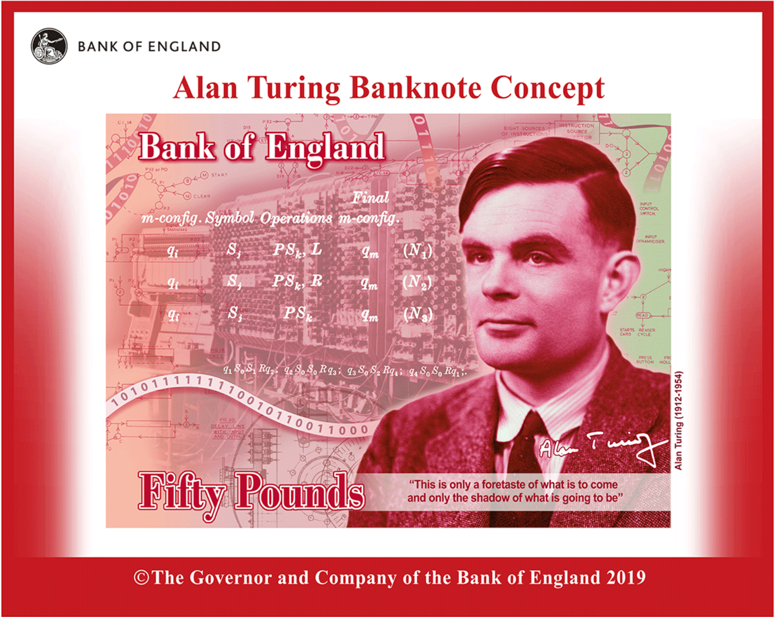
Turing's work on designing bombes was only one of his important wartime contributions to cryptanalysis. He also worked on indicator systems for Naval Enigma traffic, the Lorenz cipher machine, and voice encryption. Starting in 1937 German Naval traffic (codenamed SHARK) was encrypted with two different methods: first a combination of tables of bigram and trigram (blocks of two or three letters) to send the message indicator settings, and then with an Enigma machine. In 1942, this was further complicated with the addition of a fourth rotor. Turing worked on identifying the German Navy's indicator procedure and developed a pencil and paper technique called “Banburismus” to reduce the amount of bombe time using a statistical scoring method based on probabilities. The Lorenz cipher machine was a different type of machine cipher (codenamed TUNNY). Turing worked out a technique, known as “Turingery”, for determining the cam settings of the wheels. In 1942, Turing went to the United States to serve as a consultant for US Navy's codebreaking work on the Enigma. He also worked at Bell Labs on speech encryption techniques for telephone systems (both breaking systems and designing a secure system). When Turing returned to England in 1943, he worked on a different system for voice encryption called Delilah at Hanslope Park.

After the war, Turing continued his interest in building programmable computing machines. He designed the Automatic Computing Engine at the National Physical Laboratory, and helped to develop the Manchester computers in Max Newman's Computing Machine Laboratory at the Victoria University of Manchester. He also wrote papers on artificial intelligence and mathematical biology.
